The Port of Long Beach on Terminal Island south of Los Angeles is the second-busiest container port in the US. It handles around 15% of all imported goods, much of it with Asia.
As the Port of Long Beach was growing in importance over the past half century, the 51-year-old Gerald Desmond Bridge has faithfully been delivering thousands of daily commuters to work on Terminal Island and over what is called the Back Channel. But the old bridge’s low ship clearance was becoming a hindrance to the passage of the largest, most economical and most environmentally friendly ships plying the oceans – the huge post-Panamex vessels.
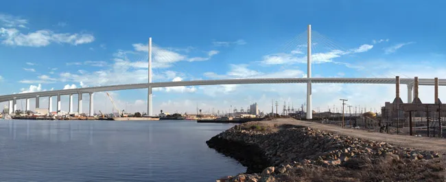
Next year the old bridge will be closed for demolition to start on its steel-arch structure. In its place will be the new cable-stayed US$828 million replacement, also called the Gerald Desmond Bridge, with more lanes and greater clearance for modern-day shipping.
When the old bridge opened in 1968, traffic was expected to be only local commuters to and from work on Terminal Island, including to the US Navy shipyard. But the Navy closed the shipyard in 1997 and much of the land was converted into a container depot, eventually becoming one of the country’s busiest terminals.
The result has been a punishing increase in traffic – much of it heavy goods vehicles – for the bridge. Average daily traffic was around 62,000 vehicles daily when the contract was signed in 2012 for the new bridge. Between 1996 and 1997 the bridge was retrofitted with vibration isolators and additional foundation work such as the widening of footings to upgrade the structure’s seismic resistance. But by 2004, port and road authorities had had to install mesh “diapers” on the bridge’s underside to catch pieces of falling concrete.
Design-wise, the old bridge’s road deck lacks emergency/breakdown lanes, meaning collisions can force the closure of traffic lanes, resulting in major congestion. Also, steep approach grades of 5.5% on the west side and 6% on the east side have meant a snarling of traffic at times.
The joint client - Port of Long Beach, California’s department of transportation (
When completed, the new bridge will be California’s first long-span cable-stayed bridge, as well as one of the tallest bridges of its kind in the US. The structure, which features two mono-pole towers with a cross section that transforms from an octagon to a diamond, is expected to become an icon for Long Beach and Southern California.
The replacement project includes approach structures and ramps, and interchanges with Ocean Boulevard and I-710 to the east, and SR-47 to the west.
Construction was expected to last five years and generate, on average, 4,000 jobs per year. But delays to construction were encountered shortly after starting work.
The site is in the middle of the Wilmington Oil Field, an old but still-producing area. There was a risk of subsidence from depleted oil reservoirs. Pier construction was delayed while further geological analysis took place. Utility lines were also relocated or removed. Meanwhile, the client and
Viscous dampers
The completed mono-pole towers of the structure highlight the inventive use of viscous dampers within the cable-stayed structure’s seismic strategy.
The 610m-long bridge carries two decks in parallel: a 305m-long cable-stayed main span and two 152m-long side spans, with a 61m clearance. The main span is supported by stays connected to two 155m-high towers that rise between the two decks, as well as four 55m-high piers, two on each side, one pier per deck. The deck itself, a steel ladder beam structure with precast post tensioned slabs, is 47m wide with an additional 3.6m of cycle path. The foundations consist of 12 drilled shafts of 2.4m diameter.
The deck of the main span is supported by a double plane of stays, 80 in total, 20 on each tower side. The HDPE-sheathed stays consist of a varying number of 1.6cm-diameter, high-strength, 270ksi strands, in anchorages that accommodate between 37 and 109 strands. The stressing ends are located at deck level while the non-stressing ends are anchored within steel boxes integral to the towers. The exceptions are the initial two levels of stays, eight per tower, which are anchored within reinforced concrete corbels on the inner face of the hollow towers.
The 900m-long west approach and the 1,155m east approach each carry two separate decks with a typical span arrangement of 64-70m.
An unusual aspect of the Gerald Desmond Bridge is its seismic design approach. This has resulted in a strategy where the deck superstructure, the towers and the approaches are each designed to perform differently during an earthquake.
In accordance with the alternative seismic strategies that are recognised in 2010 AASHTO Guide Specifications for LRFD Seismic Bridge Design, SFI/Arup decided to adopt viscous dampers for the control of the cable-stayed bridge's response to strong ground motions. This deviates from the design in the reference information documents for the bridge which assumed a split tower with ductile shear links similar to the San Francisco Oakland Bay self-anchored suspension bridge. The dampers isolate the deck superstructure from the towers and end bents during an earthquake, with the towers and end bents remaining essentially elastic both in the longitudinal and transverse directions. This completely isolates the superstructure.
In addition, ductile detailing has been provided to assure acceptable performance under earthquake shaking beyond the safety evaluation’s design basis. Ductility at two locations is designed to respond to higher order vibration modes, an important design consideration for seismic protection of tall hollow sections. The reinforcement detailing includes corner pilasters to provide confidence in the confinement and integrity of the corner regions.
Structural stops were included in the design to prevent dampers from reaching the end of their stroke in a beyond-design-basis event. This protects the dampers from damage to ensure proper performance throughout the earthquake. Explicit non-linear seismic time history analysis was carried out beyond design-basis events with scaled ground motions to prove the adequacy of the design.
The use of viscous dampers to control and attenuate superstructure forces on the towers has brought a number of benefits. For one, it has dispensed with the seismic-related need for a split tower consisting of two shafts connected by non-elastic tension links. This has opened up a different structural and architectural path - a single-shaft tower without the visual clutter of the shear links. The single closed section is neater in appearance and more cost-effective. There are no connecting elements between dual shafts that require inspection or replacement following a seismic event.
Flexible and slender
Designing the tower to be essentially elastic under California’s extreme ground motions meant it had to be very flexible and slender. The 155m-tall tower is just 9.3m across at its base. This allows the top of the tower to flex more than 2m in an earthquake without damage. However, this flexibility led to a need for thorough wind tunnel testing to ensure adequate aerodynamic performance.
Aeroelastic wind tunnel testing was carried out at Southwest Jiaotong University in Sichuan Province, China at a scale of 1:80. This large-scale testing, with a tower model nearly 2m tall, provided accurate results and showed a potential for a galloping response of the free standing tower. Although the response occurred only for a specific wind angle and for an unusual combination of high wind speed (105km/h) and low turbulence it was judged to be a risk that should be mitigated.
It was decided to install a tuned mass damper at the top of the tower. Modifications were made to the model which demonstrated that increasing the structural damping to 0.8% to critical was sufficient to eliminate the response. The dampers were installed at the top of both towers immediately after construction reached the full height. After on-site tuning of the dampers a noticeable decrease in the vibration response under wind loads was observed.
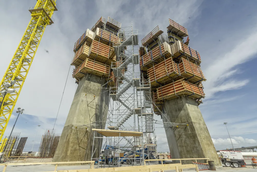
The challenge in constructing the two pylon masts (towers) lies in their octagonal design that tapers as the columns rise. Furthermore, the base – or pile cap - for each pylon is two stories high. In early 2015, formwork specialist
To execute the change in shape with each casting section, or jump, Doka provided 185m² of Top 50 formwork. The modular gang-form system can be assembled in any configuration to adapt to any shape, plus it’s easily retracted for cleaning and jump sequences. The formwork can also be used to meet stringent specifications for surface finishes, which was the case for this project.
Doka’s SKE automatic climbing platforms were used inside and outside of the pylons to jump the Top 50 formwork system in 31 casting steps. Each casting step is 5.5m high. The SKE climbing brackets enable easy hydraulic climbing without the need for cranes.
Doka met weekly with the pylon design team during the design, layout and fabrication stages. As part of this process, Doka delivered fabrication drawings to vendors, procured needed materials and equipment, sent the drawing log to the general contractor and addressed any formwork pre-assembly issues with the carpenter crew.
Individual formwork parts were pre-assembled by the Doka team to ensure tight form joints and a best-in-class joint pattern, even with the challenging geometry of the pylons. The pre-assembly team also ensured all custom components, such as splices and walers, were connected to each other correctly via preconstruction mock-ups. This resolved potential problems before the equipment reached the jobsite.
The mock-ups were especially important because of the high number of custom components required for the formwork and climbing platform configuration.
Wind design and analysis also included site-specific wind climate assessment, sectional wind tunnel testing and aeroelastic wind tunnel testing of the full bridge and maximum cantilever construction stage. No flutter instability was observed for any of the tested configurations with wind speeds up to 280km/h, well above the requirements of 195km/h in service and 162km/h during erection. A wind buffeting analysis was carried using bridge design, analysis and construction software, a Bentley RM Bridge package, which uses a frequency domain calculation based on Davenport’s theory to determine the member design forces for all structural elements.
To counter large relative displacements that accompany the uncoupling motions of the main spans and the approaches, swivel joist expansion joints are in place that can accommodate simultaneous displacements in both the longitudinal and transverse directions. The seismic time history analysis included the cable-stayed bridge and both approach bridges to determine the displacement demand on the joints and bearings.
During the construction phase a number of temporary restraints were used to prevent any undesired movement of the towers and steel structure: steel shear keys were connected to the towers; stability towers were placed between permanent towers and end bents; and temporary tuned mass dampers were located on the top of the towers.
Another innovative aspect of the project was the cast‐in‐drilled‐hole (CIDH) grout delivery system that was field-designed and tested by the project's foundations team – a first in California. The method was developed because the new bridge crosses the Wilmington Oil Field where more than 6,000 wells have been drilled since oil was discovered in 1932. Around 600 wells remain active.
The CIDH grout delivery system involves tip-grouting the pile bases to maximise the amount of weight that the end of the pile can support. The system uses the base resistance of the shaft as well as its side resistance to account for the design loading of the bridge. By providing better contact between soils and the grout, the tip grout enables the pile to be smaller, which also results in less pile drilling and the use of smaller equipment.
The project design required 351 CIDH piles, ranging from 1.5-2.4m in diameter and reaching depths of 31-56m. To drill the CIDH piles, the foundation team used casing oscillators and rotators to advance temporary steel casing through the many soil types found at the site.
Ten solid columns on the east side can be constructed only at the next stage, when north-bound traffic is circulating on the main span. At that point, the connector with Highway 710 can be demolished and the structures completed.
December 2017 saw completion of both towers.
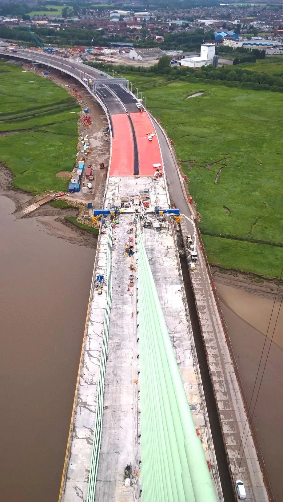
Meanwhile, work is finishing on the approach road decks. Each deck has been created using an under-lane self-launched movable scaffold system (MSS) – the first project in California to use an MSS. The two MSSs, each weighing around 1,438tonnes and designed by Norwegian engineering firm Strukturas, have a 73.7m-long main girder that slides forward to rest between two consecutive piers. Once resting on the piers the form work that is slung under the girders is moved into position to create the mold for pouring the deck’s concrete.
When the cement is poured and cured, the formwork retracts. The girder slides forward to allow its front to rest on the next pier and the process starts again.
Construction of the bridge is nearing completion with the focus on cantilever construction of the main span and on future connections with the highway network surrounding the bridge.
As World Highways went to press, the pier tables were completed around both towers that face each other across the Back Channel. Construction crews were busy attaching the next set of cables in order to build outward until each tower’s crew meets in the middle of the channel crossing.
The bridge is expected to be open later this year or early next year.
Old Gerald Desmond
The old and new bridges are named after a prominent City of Long Beach civic leader and city lawyer. Design of the old bridge was by Moffat & Nichol and construction by Bethlehem Steel. The roadway is essentially five lanes but is configured with four lanes - two in each direction – and a fifth acting as a climbing lane on each end of the bridge.
*Technical detail for this article has been written by Matt Carter, a principal in the New York office of the project’s design engineering firm Arup. Carter, Arup’s Americas Region Bridge and Civil Structures Skills leader, is a graduate of Cambridge University in the UK and has 20 years of experience in the design and construction of long-span and complex bridge structures globally. He served as engineer of record for the design of the Gerald Desmond Bridge Replacement Project.
Carter’s other projects include the Temburong Crossing in Brunei, Incheon Bridge in South Korea and the Second Penang Bridge in Malaysia, Stonecutters Bridge in Hong Kong, the Marina Bay Sands Skypark in Singapore and the Hong Kong-Zhuhai Macau Bridge. He was instrumental in the development of the concept design of the Queensferry Crossing in Scotland (see World Highways, key project report, November 2016).