Mexico will benefit from an important new underwater tunnel - Mauro Nogarin writes. The city of Coatzacoalcos is located at the mouth of the river of the same name, in the Gulf of Mexico, 302km from the city of Salina Cruz, Oaxaca, in the east end of trans-isthmian corridor and at the southern end of Veracruz State. The city is seeing a key development as currently construction is 85% completed on the first immersed tube, underwater tunnel in Latin America.
The reasons why experts chose this type of tunne
Mexico will benefit from an important new underwater tunnel - Mauro Nogarin writes
The city of Coatzacoalcos is located at the mouth of the river of the same name, in the Gulf of Mexico, 302km from the city of Salina Cruz, Oaxaca, in the east end of the trans-isthmian corridor and at the southern end of Veracruz State. The city is seeing a key development as currently construction is 85% completed on the first immersed tube underwater tunnel in Latin America.
The reasons why experts chose this type of tunnel were based on the fact that in this area the urban, commercial and tourism development is extremely limited to the north by the Gulf of Mexico. In addition to the south the swampy ground means that suitable soils are scarce and expensive. The alternative of a new cable-stayed bridge would have meant higher costs of conservation and maintenance, while the driven tunnel option was discarded because it was considered technically unfeasible due to the required depth, the length of the ramps and the marshy ground.
The Coatzacoalcos tunnel represents a technological innovation in the field of construction, since the immersed-tunnel method technique allows prefabrication in a dry dock of reinforced concrete tunnel sections. These can later be prepared for flotation and be towed and placed at the bottom of a seabed without having to use special underground drilling equipment.
The work consists of building a road 2,280m long and four lanes wide, two lanes for each direction. The road is 3.5m in width in the open section and 3.75m in width in the underground tunnel section with a shoulder of 1m.
The area is home to the major oil refineries and petrochemical complexes in the country such as the plants at Morelos, Pajaritos and Cangrejera and the Cosoleacaque Petrochemical Complex and Minatitlan Refinery.
More than 14,500 cars/day and 3,500 trucks/day currently transit from the industrial areas to the urban areas by means of river ferries or by using the two-lane Coatzacoalcos I bridge. But this causes traffic jams and delays of 45 minutes to cross from shore to shore. In addition, over 8,000 pedestrians who do not have vehicles use river ferries to cross the Coatzacoalcos River from Allende to Coatzacoalcos every day. When there is bad weather ferry traffic comes to a complete stop, causing further congestion. Construction of the underwater tunnel beneath the Coatzacoalcos River is the best solution as a public works project to solve these logistical problems. The project will be financed with a combination of public and private resources that will total an investment of around US$330 million.
The geology of the site where the tunnel is being constructed consists of marine deposits (coastal), fluvial (river) and fluvial-lacustrine. These soils range from very soft to very stiff/hard clay and fine sand showing various degrees of compaction and cementation. Three layers that make up the tunnel geotechnical profile were defined: superficial silty sand, silt/clay and deep sand, this is a geotechnical subsurface soil charting based on linear interpolation between drilling and assay to confirm the nature of the alluvial soils.
The underwater tunnel cuts through alluvial formations and crosses the Coatzacoalcos River from the left bank, where the city of Coatzacoalcos is located, to the right bank where the town of Allende is situated. The first cut and cover stretch on the Coatzacoalcos side begins in granular soil and descends into cohesive soil before entering the deeper layer of tight sands. When the underwater tunnel emerges again on the Allende side of the river it once again enters cohesive soil and a transitional area of surface sands.
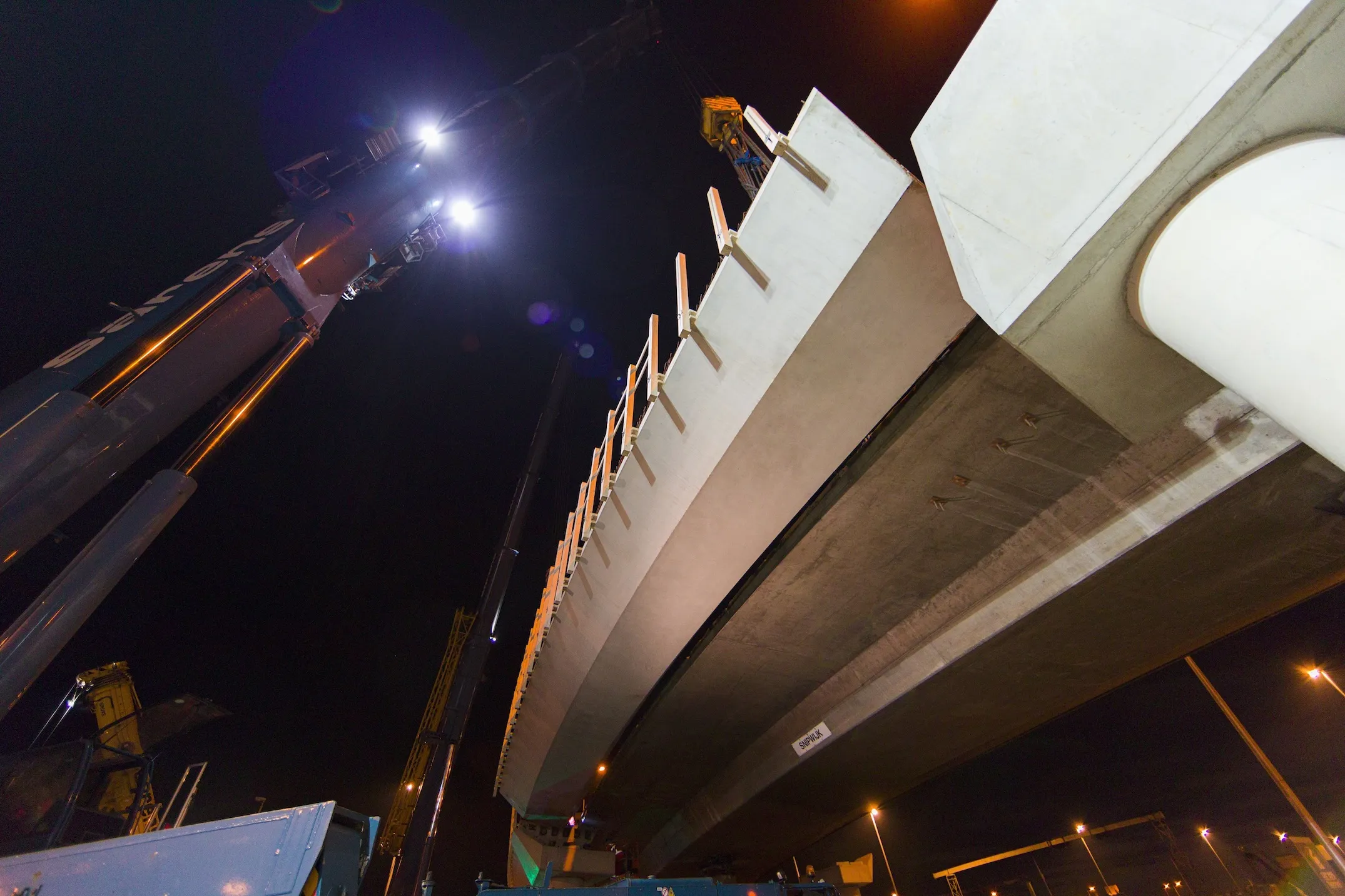
The tunnel features a submerged component made of longitudinally prestressed reinforced concrete and has a total length of 1,149m. Of this length, 696m form the underwater structure and the remaining 453m is the cut and cover stretch on land. The cross section measures 5.1m×9.2m and carries four lanes into two separate tubes, plus a section for emergency exit and special facilities. The tunnel runs 30m below the surface of the riverbed and is composed of four segments, each 138m in length. These were prefabricated in an 11.5m deep dry dock and covered an area of 12.5ha. During the 1.5 million m3 excavation to build the dry dock, pumping was required to lower the water table. During this process, the slopes were constantly monitored every 4m. Once the required depth was achieved, the slopes were covered with an HDPE and geotextile special membrane to prevent landslides and protect them. Although the dry dock installations were only temporary, they were built to permanent installation safety parameters due to the importance of the work being done.
Once the segments were completed and before the ends were sealed, the dry dock was flooded to allow flotation of the segments. In order to facilitate the transfer of the segments it was necessary to build a canal that connected the dry dock to the river, through which the segments were towed to their final location. At the construction site, the area had been prepared for their installation by previously dredging the river bottom to the necessary depth. Once the segments were connected, they could be covered.
The construction of each element was first carried out by casting the bottom slab, to a thickness of 1m; afterwards the interior walls were cast, also in sections, and finally the exterior walls and upper slab. This process was repeated for sections 2 through 5, since the end sections had to be constructed during the final stages. Each of these elements weighed 27,000tonnes. Once the sections were completed, the ends were sealed with temporary walls to keep them watertight during the flotation and submersion phase. In addition, four tanks were installed in each section that could be filled with water, to facilitate sinking and ensure they sank to their final resting position at the bottom of the river.
DATA
Dam:
Excavation 1,428,111m3
Bentonite-cement walls 32,064m2
Polyethylene sheet against slope protection 73,009m2
geotextile membrane 120,934m2
Permanent structure:
Dredging 1,220,000m3
Slurry walls of 1 m. thickness 26,458m2
corrugated steel bars 22,346,000kg
Steel wire for PRESTRESSED CONCRETE 572,742kg
Precast concrete 56,669m3
Concrete in Structures Ramps 30,675m3
Fire resistant panels 27,816m2
Filling Material 220,000m3Construction of the access ramps was simultaneous with the construction of the underwater elements. These access ramps were built all along the length of the tunnel with 3m high buttresses and 6m cant to enable the placement of the submersible segments at a depth of 15-24m below the surface of the river. The tunnels deepest submerged portion was located at a depth of 30m below the surface of the river, some 15m below the deepest part of the riverbed.
The two portals to the tunnel on the eastern and western shores of the river house the mechanical and electrical installations of the tunnel. At the toll entrance to the tunnel an administration building was built. The tunnel has all the facilities and systems necessary for proper operation and control including electrics, ventilation, CO detection, emergency, fire detection, variable signage, CCTV, PA and a comprehensive security system, with video surveillance and control in real time, ensuring efficient management and safety for the users.
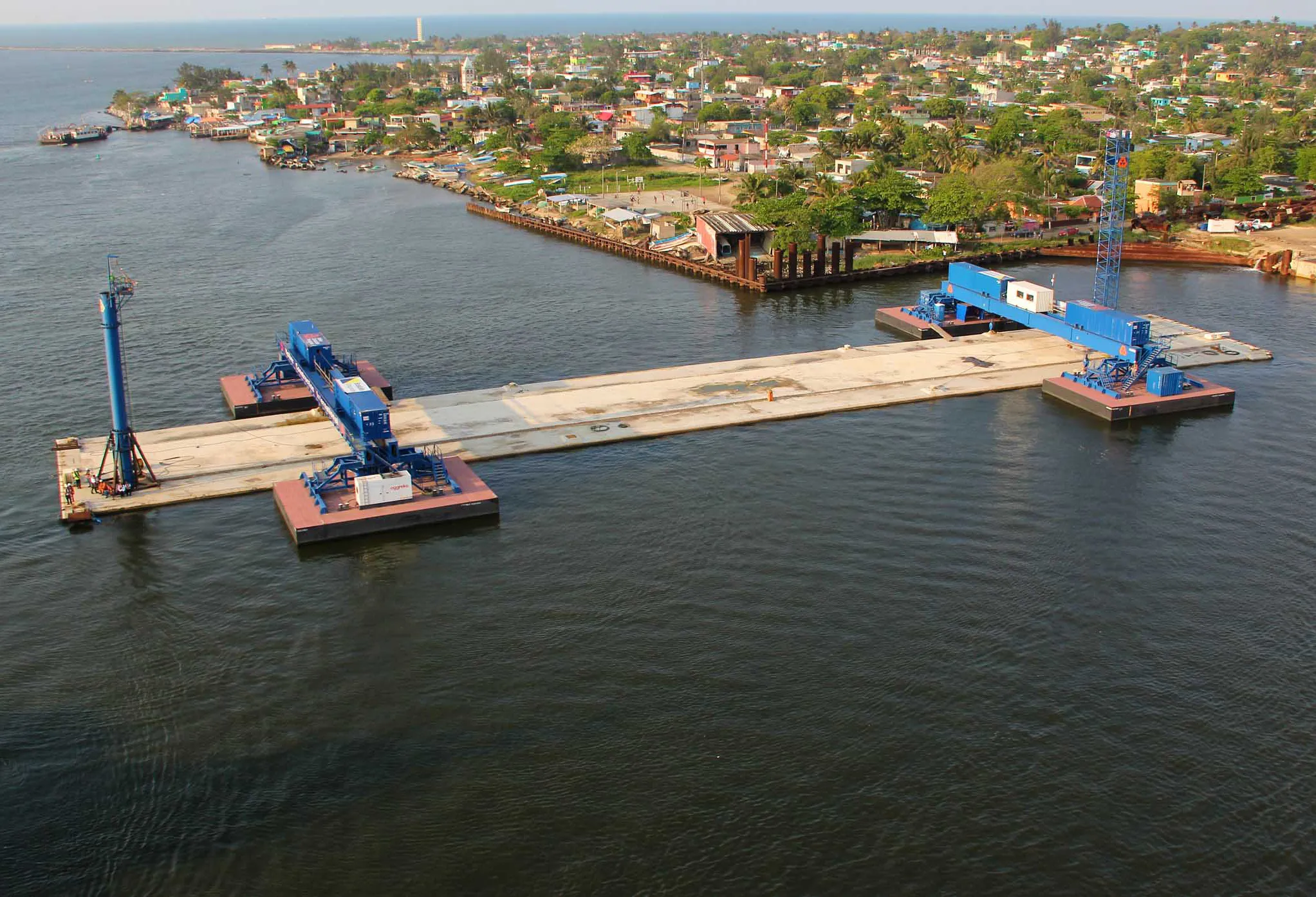
Modular Catamaran
Once the elements were floated out of the dock to their final location, it was critical that the immersion technique was applied correctly.
VolkerCI specifically designed, built and used the new immersion equipment for this project: the modular catamaran. The modular system helps to expand or reduce its capacity. During the immersion of the elements the catamaran proved to be functioning very well and was stable, according to design.
The catamaran made sure that each piece was lowered into place on the gravel bed, aligned correctly for a smooth join up.
The city of Coatzacoalcos is located at the mouth of the river of the same name, in the Gulf of Mexico, 302km from the city of Salina Cruz, Oaxaca, in the east end of the trans-isthmian corridor and at the southern end of Veracruz State. The city is seeing a key development as currently construction is 85% completed on the first immersed tube underwater tunnel in Latin America.
The reasons why experts chose this type of tunnel were based on the fact that in this area the urban, commercial and tourism development is extremely limited to the north by the Gulf of Mexico. In addition to the south the swampy ground means that suitable soils are scarce and expensive. The alternative of a new cable-stayed bridge would have meant higher costs of conservation and maintenance, while the driven tunnel option was discarded because it was considered technically unfeasible due to the required depth, the length of the ramps and the marshy ground.
The Coatzacoalcos tunnel represents a technological innovation in the field of construction, since the immersed-tunnel method technique allows prefabrication in a dry dock of reinforced concrete tunnel sections. These can later be prepared for flotation and be towed and placed at the bottom of a seabed without having to use special underground drilling equipment.
The work consists of building a road 2,280m long and four lanes wide, two lanes for each direction. The road is 3.5m in width in the open section and 3.75m in width in the underground tunnel section with a shoulder of 1m.
The area is home to the major oil refineries and petrochemical complexes in the country such as the plants at Morelos, Pajaritos and Cangrejera and the Cosoleacaque Petrochemical Complex and Minatitlan Refinery.
More than 14,500 cars/day and 3,500 trucks/day currently transit from the industrial areas to the urban areas by means of river ferries or by using the two-lane Coatzacoalcos I bridge. But this causes traffic jams and delays of 45 minutes to cross from shore to shore. In addition, over 8,000 pedestrians who do not have vehicles use river ferries to cross the Coatzacoalcos River from Allende to Coatzacoalcos every day. When there is bad weather ferry traffic comes to a complete stop, causing further congestion. Construction of the underwater tunnel beneath the Coatzacoalcos River is the best solution as a public works project to solve these logistical problems. The project will be financed with a combination of public and private resources that will total an investment of around US$330 million.
The geology of the site where the tunnel is being constructed consists of marine deposits (coastal), fluvial (river) and fluvial-lacustrine. These soils range from very soft to very stiff/hard clay and fine sand showing various degrees of compaction and cementation. Three layers that make up the tunnel geotechnical profile were defined: superficial silty sand, silt/clay and deep sand, this is a geotechnical subsurface soil charting based on linear interpolation between drilling and assay to confirm the nature of the alluvial soils.
The underwater tunnel cuts through alluvial formations and crosses the Coatzacoalcos River from the left bank, where the city of Coatzacoalcos is located, to the right bank where the town of Allende is situated. The first cut and cover stretch on the Coatzacoalcos side begins in granular soil and descends into cohesive soil before entering the deeper layer of tight sands. When the underwater tunnel emerges again on the Allende side of the river it once again enters cohesive soil and a transitional area of surface sands.
The tunnel features a submerged component made of longitudinally prestressed reinforced concrete and has a total length of 1,149m. Of this length, 696m form the underwater structure and the remaining 453m is the cut and cover stretch on land. The cross section measures 5.1m×9.2m and carries four lanes into two separate tubes, plus a section for emergency exit and special facilities. The tunnel runs 30m below the surface of the riverbed and is composed of four segments, each 138m in length. These were prefabricated in an 11.5m deep dry dock and covered an area of 12.5ha. During the 1.5 million m3 excavation to build the dry dock, pumping was required to lower the water table. During this process, the slopes were constantly monitored every 4m. Once the required depth was achieved, the slopes were covered with an HDPE and geotextile special membrane to prevent landslides and protect them. Although the dry dock installations were only temporary, they were built to permanent installation safety parameters due to the importance of the work being done.
Once the segments were completed and before the ends were sealed, the dry dock was flooded to allow flotation of the segments. In order to facilitate the transfer of the segments it was necessary to build a canal that connected the dry dock to the river, through which the segments were towed to their final location. At the construction site, the area had been prepared for their installation by previously dredging the river bottom to the necessary depth. Once the segments were connected, they could be covered.
The construction of each element was first carried out by casting the bottom slab, to a thickness of 1m; afterwards the interior walls were cast, also in sections, and finally the exterior walls and upper slab. This process was repeated for sections 2 through 5, since the end sections had to be constructed during the final stages. Each of these elements weighed 27,000tonnes. Once the sections were completed, the ends were sealed with temporary walls to keep them watertight during the flotation and submersion phase. In addition, four tanks were installed in each section that could be filled with water, to facilitate sinking and ensure they sank to their final resting position at the bottom of the river.
DATA
Dam:
Excavation 1,428,111m3
Bentonite-cement walls 32,064m2
Polyethylene sheet against slope protection 73,009m2
geotextile membrane 120,934m2
Permanent structure:
Dredging 1,220,000m3
Slurry walls of 1 m. thickness 26,458m2
corrugated steel bars 22,346,000kg
Steel wire for PRESTRESSED CONCRETE 572,742kg
Precast concrete 56,669m3
Concrete in Structures Ramps 30,675m3
Fire resistant panels 27,816m2
Filling Material 220,000m3Construction of the access ramps was simultaneous with the construction of the underwater elements. These access ramps were built all along the length of the tunnel with 3m high buttresses and 6m cant to enable the placement of the submersible segments at a depth of 15-24m below the surface of the river. The tunnels deepest submerged portion was located at a depth of 30m below the surface of the river, some 15m below the deepest part of the riverbed.
The two portals to the tunnel on the eastern and western shores of the river house the mechanical and electrical installations of the tunnel. At the toll entrance to the tunnel an administration building was built. The tunnel has all the facilities and systems necessary for proper operation and control including electrics, ventilation, CO detection, emergency, fire detection, variable signage, CCTV, PA and a comprehensive security system, with video surveillance and control in real time, ensuring efficient management and safety for the users.
Modular Catamaran
Once the elements were floated out of the dock to their final location, it was critical that the immersion technique was applied correctly.
VolkerCI specifically designed, built and used the new immersion equipment for this project: the modular catamaran. The modular system helps to expand or reduce its capacity. During the immersion of the elements the catamaran proved to be functioning very well and was stable, according to design.
The catamaran made sure that each piece was lowered into place on the gravel bed, aligned correctly for a smooth join up.